


EKG SIMULATOR WITH ARDUINO :)
- Nathalia, Angie, Dayan.
- 16 ago 2018
- 4 Min. de lectura

Actualizado: 2 oct 2018

DEVELOPMENT
Four EKG vectors, with different pathologies, were downloaded from the physioNet page.
Normalization of vectors in excel.
-The vectors were cut so that the minimum number of data possible remained, without losing any wave of the signal.
-The value of the smallest number was subtracted from each vector number, if the smallest number was negative, it was added until the smallest number of the vector was 0.
-Each number in the vector was divided by the largest number, so that the largest number in the vector was 1.
-Each vector number was multiplied by 255 (the largest number of eight bits).
-The decimals of all the numbers were removed.
Code in arduino
-Variable configuration.
-Four variables were configured as integers, assigning each one a digital port, from 9 to 12.
-4 variables were configured as double, 2 variables were assigned ports, A0 and A1, analog ports were assigned because these variables were potentiometers. -The 4 vectors were defined.

Void setup -The potentiometry, potentiometer that would vary the amplitude, and the frequency potentiometer were defined as input variables. -The four variables defined above were defined as entries.
-Port D was defined as output. -The arduino transmission speed of 115200 baud was selected.

Void loop
The entries that select any of the four electrocardiogram signals are read and stored in a variable. then the value of the input where the amplitude potentiometer is read and stored in variable a is read, if any input that selects the electrocardiogram signal is set to 1, the program enters a cycle that starts at position 1 of the vector, to the last position in 1-in-1 jumps; in the variable aa sedivides the value of the variable (a) by 1023 (maximum number reached by the potentiometer) so that the value of maximum amplitude is 1, the multiplication of each number of the vector by the value is printed in port D of the variable aa, varying the amplitude of the signal that comes out of port D. When it leaves the cycle, port D is equal to the multiplication of the last number of the vector by the variable aa to maintain the axis of the signal. Then the program enters a function called frequency; where in the variable Y saves what is read in the frequency potentiometer, and then makes a cycle that starts at position 1, goes to the value that the frequency potentiometer read and increases from 1 to 1, in the cycle there is a delay of 1 ms.


Let's see the circuit to can prove it!!!!!
Digital-Analog Conversion
now to work with a digital signal we do a R2R ladder like alternative to the binary-weighted-input DAC. Using the next ressistor configuration in the output of digital PORTD of
Arduino

NOTCH FILTER DESIGN
Mathematical calculations for filter design
A Notch filter with a bandwidth of 50Hz-70Hz and a resonance frequency of 60Hz is designed, for its mathematical analysis a value is assigned to the capacitor (C1) and its resistors and capacitor 2 (C2) are calculated:


now you can do the circuit to prove the signal of output
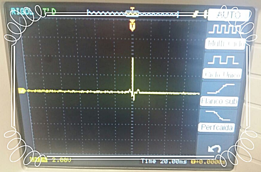
Now we show you the acquired signals with the selected vector


As you can see, the R2R connection allows us to acquire data from a DIGITAL output and transform it to analogue, in order to obtain a signal in the time evaluated in the oscilloscope.
The last step, for simulate a real signal, we take one signal and aplly a sine noise of 60 Hz to prove the notch filter and as you can see to continuation we obtain:


the sine noise "ates" the original signal but the Notch filter, helps to avoid the noise and adquire a original signal
GLOSARY
*Band Stop Filter: (BSF) is another type of frequency selective circuit that functions in exactly the opposite way to the Band Pass Filter we looked at before. The band stop filter, also known as a band reject filter, passes all frequencies with the exception of those within a specified stop band which are greatly attenuated. [1]
* Arduino: is an open-source electronics platform based on easy-to-use hardware and software. [2]
* The electrocardiogram (ECG or EKG):is a diagnostic tool that is routinely used to assess the electrical and muscular functions of the heart. While it is a relatively simple test to perform, the interpretation of the ECG tracing requires significant amounts of training. Numerous textbooks are devoted to the subject.
*TRIGGER: The main utility of a trigger is to improve the administration of the database, since it does not require a user to execute them.
*BIT: A bit is a digital of the binary numbering system. *LADDER: It is a very popular graphic programming language within programmable automata because it is based on classic electrical control schemes. Bibliographic references
[1]Electronics-tutorials. (2015). Band Stop Filter. [online] Available at: https://www.electronics-tutorials.ws/filter/band-stop-filter.html [Accessed 16 Aug. 2018].
[2]"Arduino - Introduction", Arduino.cc, 2018. [Online]. Available: https://www.arduino.cc/en/Guide/Introduction. [Accessed: 16- Aug- 2018].
[3] F. Benjamin Wedro, "What is an Electrocardiogram (ECG, EKG)?", eMedicineHealth, 2018. [Online]. Available: https://www.emedicinehealth.com/electrocardiogram_ecg/article_em.htm. [Accessed: 17- Aug- 2018].


Comentarios